
Repairing a Fluke 6080A RF Signal Generator
Background
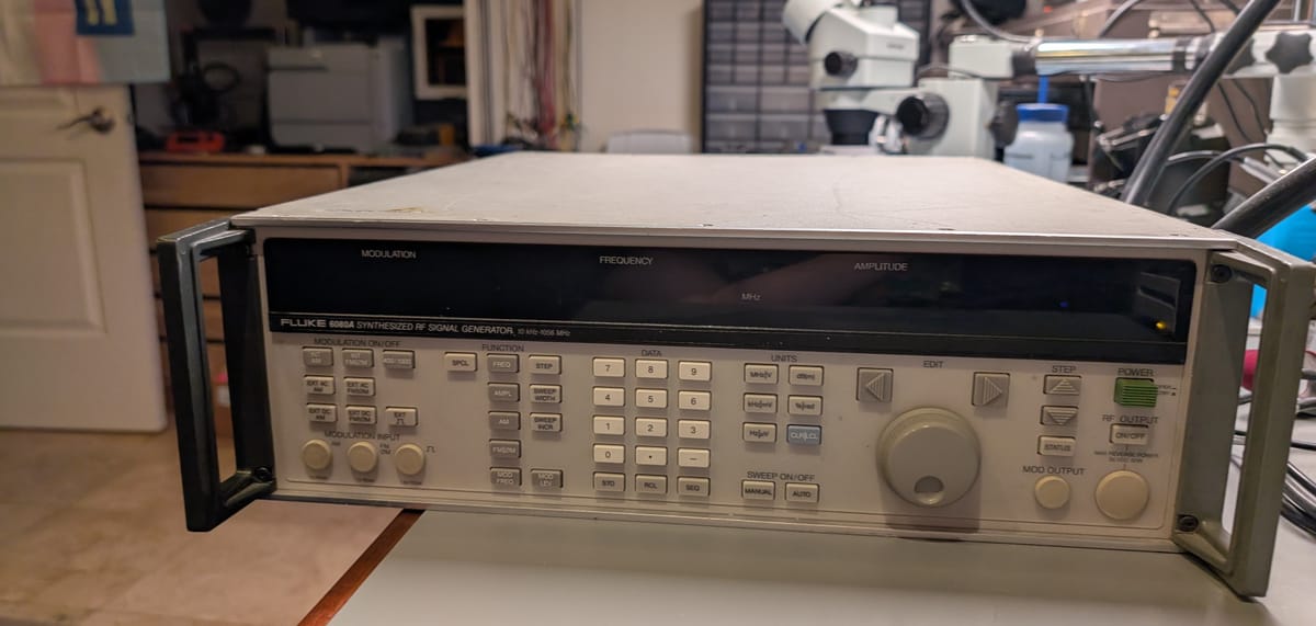
A few years back, a local company was liquidating some old lab equipment at auction, including a used Fluke 6080A Synthesized RF Signal Generator. I had some project ideas that could use an RF signal source that could generate modulated waveforms, the price was right, and it seemed to be in good condition.
A couple bids later, and I was the proud new owner of a 60 pound, 1990's-vintage signal generator. I played around with it for a bit, proved to myself that it worked, checked that the output spectrum looked reasonable and that the modulation modes functioned, then put it in storage.
The first real use the signal generator got was as a signal source to complete an alignment for a Heathkit SB-101 transceiver I was rebuilding, and while the signal generator worked flawlessly at first, I started running into an issue where it would randomly power off. Repeatedly power-cycling it generally brought it back to life, and leaving it unplugged for a longer time would reliably revive it. I managed to limp it through the testing I needed to do, then put it back in storage.
Eventually, I added a 4-post rack to my lab, giving the signal generator a permanent home. Unfortunately, this led to the power issue becoming much more noticeable. Leaving the signal generator plugged into mains for an extended time would almost always lead to it not powering on.
Initial debug
The failure mode for the instrument was simple and easily reproducible: if the signal generator was left plugged in for an extended time (several hours to overnight), it wouldn't turn on when the power switch was pressed. If I left it unplugged for an hour or so, it would power up without issues. When it did power up, it would pass its self-test with no errors and function perfectly.
Fortunately, full schematics and component-level repair information is available from KO4BB's excellent archive of manuals, making troubleshooting significantly easier.
This sounded very much like a power supply issue, and the time-dependent nature of it sounded like a semiconductor problem. I've had equipment with faulty transistors exhibit similar behavior. As it heats up, the transistor's beta drops, causing them to not operate as expected in the circuits they're in. When the circuit cools back down, it behaves normally again.
The Fluke 6080A has 9 system power supplies provided from the power supply PCB:
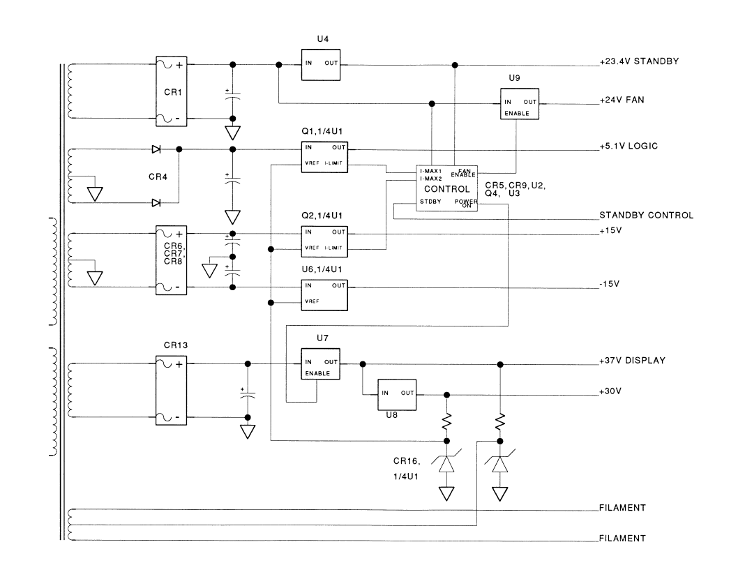
- +23.4V Standby - powers housekeeping circuitry while the unit is off, including the oven for the ovenized reference oscillator. Also powers amplifiers and circuitry on the power supply PCB.
- -5V Standby - powers amplifiers and circuitry on the power supply PCB.
- VFD filament voltage - always-on
- +24V Switched - powers the rear cooling fan and some of the system electronics.
- +5.1V Switched - high current 5.1V supply for the digital logic. Overcurrent protected.
- +15V Switched - high current 15V supply for analog circuitry in the system. Overcurrent protected.
- +30V Switched - powers analog circuitry in the system.
- +37V Switched - powers analog circuitry in the system.
There were a few reasons I could think of for why the supply wouldn't turn on
- The power switch was in the "standby" position (or faulty, so it never electrically left the "standby" position).
- The +23.4V or -5V standby supplies were either not present or not regulating correctly.
- A fault on either the +5.1V or +15V switched rails caused an overcurrent condition, triggering the overcurrent protection crowbar to latch on until the power supply was returned to "standby" for several minutes.
Before opening the case, I could tentatively rule out 2 and 3. The +23.4V supply also powers a standby LED on the front panel. That LED was lit, suggesting the +23.4V standby supply was okay.
I suspected an overcurrent fault wouldn't be instantaneous - other supplies in the system would power up briefly, including the +24V supply for the cooling fan. Watching the fan while pressing the power switch, there was no movement of the rotor, suggesting that none of the switched supplies were powering on, and pointing away from an overcurrent fault.
Opening the Case
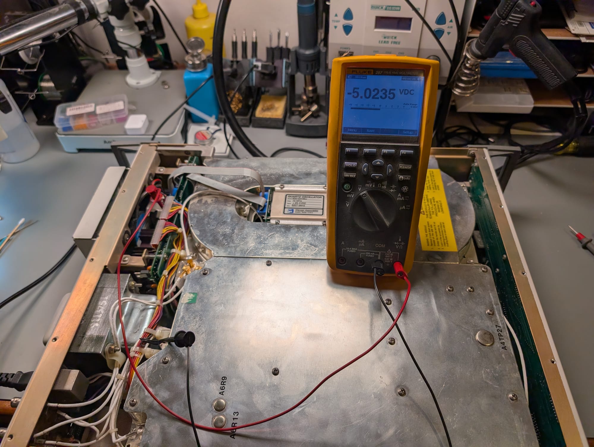
I opened up the signal generator to test further. Annoyingly, for packaging reasons, Fluke located the power supply board at the very back of the chassis in a location that requires removing the entire back panel in order to access all of the available test points. Enough were accessible without the back panel removed to allow some quick voltage checks, though.
With the power switch off, both the +23.4V and -5V standby supplies checked out within their expected ranges at 24.066V and -5.023V, respectively.
With the power switched on, both standby supplies stayed on at roughly the same voltage, but the remaining power supplies did not start up.
| Supply | Expected Voltage | Measured Voltage |
|---|---|---|
| +23.4V Standby | 24V ±5% | 24.08V |
| -5V Standby | -5V ±5% | -5.023V |
| +24V | 24V ±5% | 3.4V (fluctuates, rising) |
| +5.1V | 5.1V ±2% | 0.127V |
| +15V | 15V ±4% | -0.3V |
| -15V | -15V ±4% | 0.175V |
| +37V | +37V ±5% | -0.58V |
| +30V | +30V ±5% | -0.14V |
| +5V Reference | +5V ±3% | -0.104V |
Partway through measuring, the 24V fan suddenly turned on, albeit not at full speed. Re-measuring the +24V supply showed it to now be at ~5.6V.
Digging Deeper
Let's take a look at the power supply schematics for a little more context:
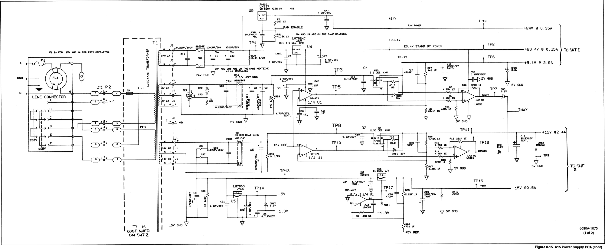

The startup sequence for the power supply is controlled by U3, an LM339 open-drain comparator, and associated components on sheet 2.
Going forward, I'll use the following convention when discussing U3:
- The rightmost block with pins 6, 7, and 1, I'll call U3-1 or U3 part 1.
- The left side top block with pins 2, 4, and 5, I'll call U3-2 or U3 part 2.
- The left side middle block with pins 10, 11, and 13, I'll call U3-4 or U3 part 4.
- The left side bottom block with pins 8, 9, and 14, I'll call U3-3 or U3 part 3.
When the power switch is turned on, the STNDBY signal is pulled to ground. U3-3, now seeing 0V on its '-' input and ~5.99V on its '+' input, goes high, allowing the +24V regulator (Sheet 1, U9) to turn on. U3-4 behaves identically, removing one of two pulldowns from the '-' input of U3-1.
With the +24V regulator on, the voltage at TP22 (the overcurrent crowbar) begins to rise. When it exceeds ~6V, U3-2's output also goes high, allowing the '-' input of U3-1 to rise. When this happens, U3-1's '-' input goes above its '+' input, causing its output to actively drive low, turning off transistor Q5 and enabling +37V regulator U7 (The schematic shows an additional connection from Q1 to the +5V reference circuit, but this is not present on my unit).
If an overcurrent event occurs on either the +5.1V or +15V supplies, the offending supply's current sense amplifier (1/2 of U2 in the schematic above) will cause its corresponding Zener diode to break down, pulling the IMAX line up and triggering SCR Q4, which pulls TP22 to ground. That causes U3-2 to drive low and U3-1 to float high, turning on Q5 and disabling the majority of the power supply.
Ruling out Overcurrent
According to the service manual, a voltage less than 1V at TP22 would indicate an overcurrent fault had occurred. I measured that test point and found 5.9V, indicating no overcurrent fault.
At this stage of troubleshooting, I hadn't done the above deep dive into the circuit to realize that +5.9V would be below the threshold for U3-2 and inhibit the remaining power supplies from starting up.
Troubleshooting the +24V supply
To dig deeper, I removed the entire back panel assembly, including the power supply PCB and the mains transformer, from the chassis.
The clearest fault at this point was the out-of-regulation +24V supply, so I decided to work on that first.
The +24V supply is a classic LM317 design. R7 and R31 form a divider network, scaling up the +1.25V reference voltage between U9's OUT and ADJ pins to 24V. Tantalum capacitor C48 provides a soft-start delay to reduce inrush current. A failure in any of these components could cause a loss of regulation.
I removed all 3 from the PCB and measured them:
- R7: should be 267Ω, measured 266.6Ω - within spec.
- R31: should be 4.75kΩ, measured 4.736kΩ - also within spec.
- C48: should be 10µF, measured 10µF and 1Ω of ESR, which appeared perfectly functional
On a whim, I decided to measure resistance across C48 and found a lower-than-expected initial resistance which decreased as the capacitor charged. Testing that part further with a power supply and ammeter showed it failing low-impedance with increasing voltage.
I replaced C48 with 2 4.7µF, 50V ceramic capacitors, re-tested the board, and found all supplies powered up as expected.
I opted for a ceramic capacitor to eliminate the reverse bias concern. Swapping a modern ceramic capacitor in place of a tantalum or electrolytic capacitor is not always a good idea. The low ESR of modern ceramic capacitors can cause instability with older LDO regulators, and in some cases, designs relied on the higher ESR of a tantalum or electrolytic capacitor for damping to help avoid resonance.
In this case, the capacitor is used to provide a soft start. It's isolated behind the feedback divider resistance, so variations in its own ESR have very little impact on the regulator's stability. Substituting a ceramic capacitor should be completely acceptable in this case.
After reinstalling the power supply into the unit, it worked without issue, and the signal generator is now back in its home in my rack.
What went wrong?
I suspect the issue here was accumulated electrical overstress over time, since Tantalum capacitors are notoriously fragile under reverse bias conditions. When the power supply is turned off, U3-4 pulls C48 and the adjust pin of U9 to -1.3V in order to fully disable U9's output. That small negative bias on C48 eventually caused it to break down and fail. That failure wasn't catastrophic, and was able to heal itself over time, so if the instrument was unpowered for a long time, the failure disappeared until C48 was stressed again.
When the capacitor broke down, it caused a voltage shift in the +24V output. That output is used as the reference for the overcurrent crowbar, and so, when the +24V fell below ~6V, the power supply comparators considered this an overcurrent fault and inhibited the remaining power supplies from turning on.