Repairing an Anritsu MS4630A Network Analyzer
I've been wanting a good low-frequency network analyzer for a while now. They're tremendously useful for validating stability of power supplies and amplifiers, or for measuring the impedance of components around the lab.
I had hoped to find a good deal on a used Bode 100, which can span 1Hz to 50MHz, but they're not common on the secondhand market, and I wasn't in a rush to run out and drop $6k on a new one.
One day, I was idly browsing around on eBay when a saved search turned up a used for parts/not working Anritsu MS4630A 10Hz-300MHz Network Analyzer. The listed capabilities looked solid, and after getting a notification of a price drop offer from the seller, I was even more interested.
The listing showed the instrument powered up and passing all self-tests, but the seller wasn’t able to test it any further than that. I took a gamble, reasoning that any issues that would prevent the instrument working would also cause a self-test failure. Less than a week later a large package showed up at my door.
The Trouble Begins
Unfortunately, upon powering it up I found that while it passed self-tests without issue, the instrument simply refused to sweep. I assumed that there was a setting mis-configured, reset the instrument to factory default settings, and still couldn't find any reason it wouldn't be sweeping as expected.
The Rough Architecture
Anritsu has not released a service manual, schematics, or even a block diagram for this instrument, so all troubleshooting was blind: reverse engineering parts of the design, then measuring based on that reverse engineering to try and diagnose the fault. This section is meant to sketch a rough outline of the overall architecture of the MS4630A.
The MS4630A is designed around a backplane system, with dedicated boards handling each function in the design. A DSP module, Main CPU module, and Display CPU module handle the digital control for the instrument. A separate smaller PCB contains logic for the rear-panel interfaces. The RF deck consists of an Local module, Output module, and two identical Receiver modules.

The Local module implements the local oscillator (LO) that generates the swept tuning signal used by the Output module to generate the output signal sent to the front panel, and by the Receiver modules to downconvert the received signal at each of the two inputs.
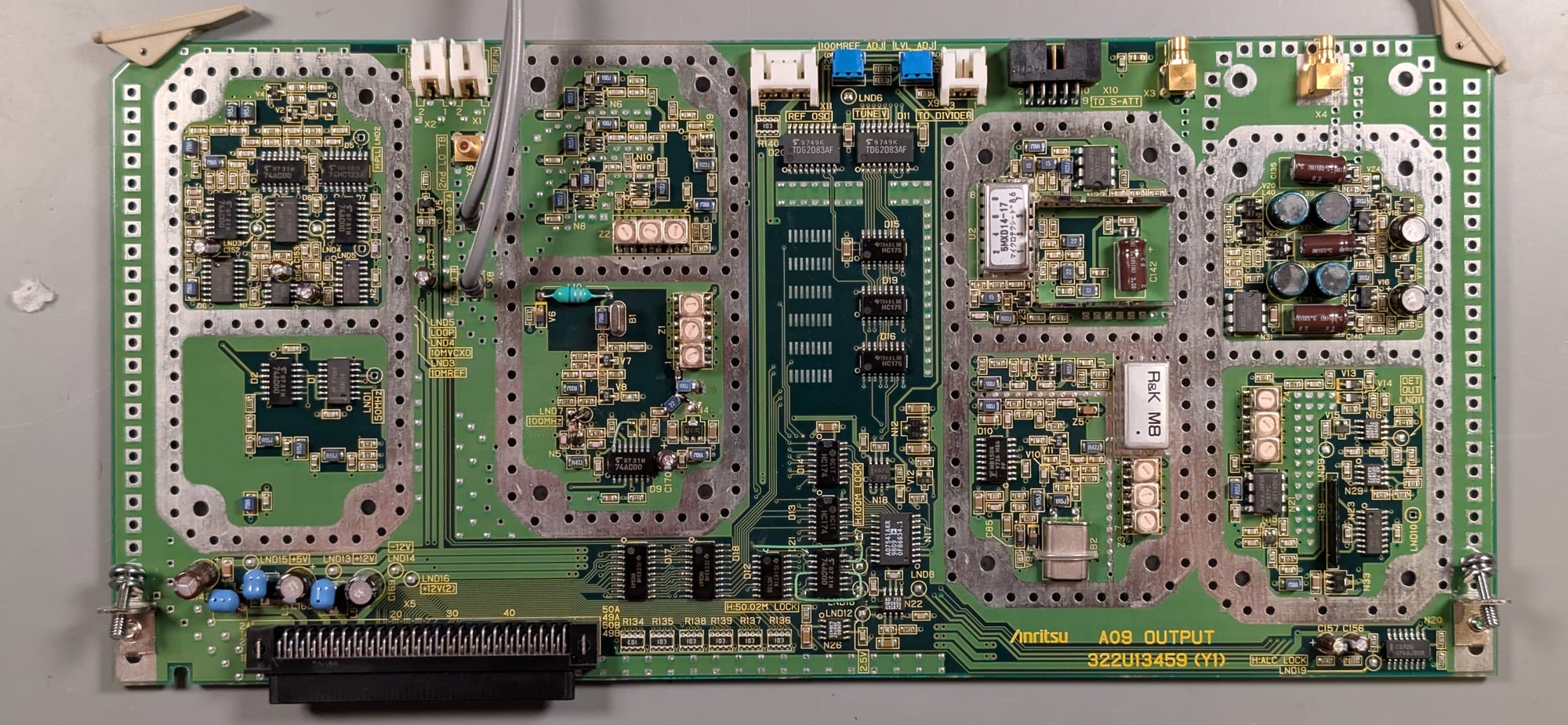
The output module contains PLLs that generate the fixed reference signals for the other RF modules, and contains the mixers and automatic level control circuit to maintain a consistent signal amplitude at the front panel output over the 10Hz to 300MHz sweep range.
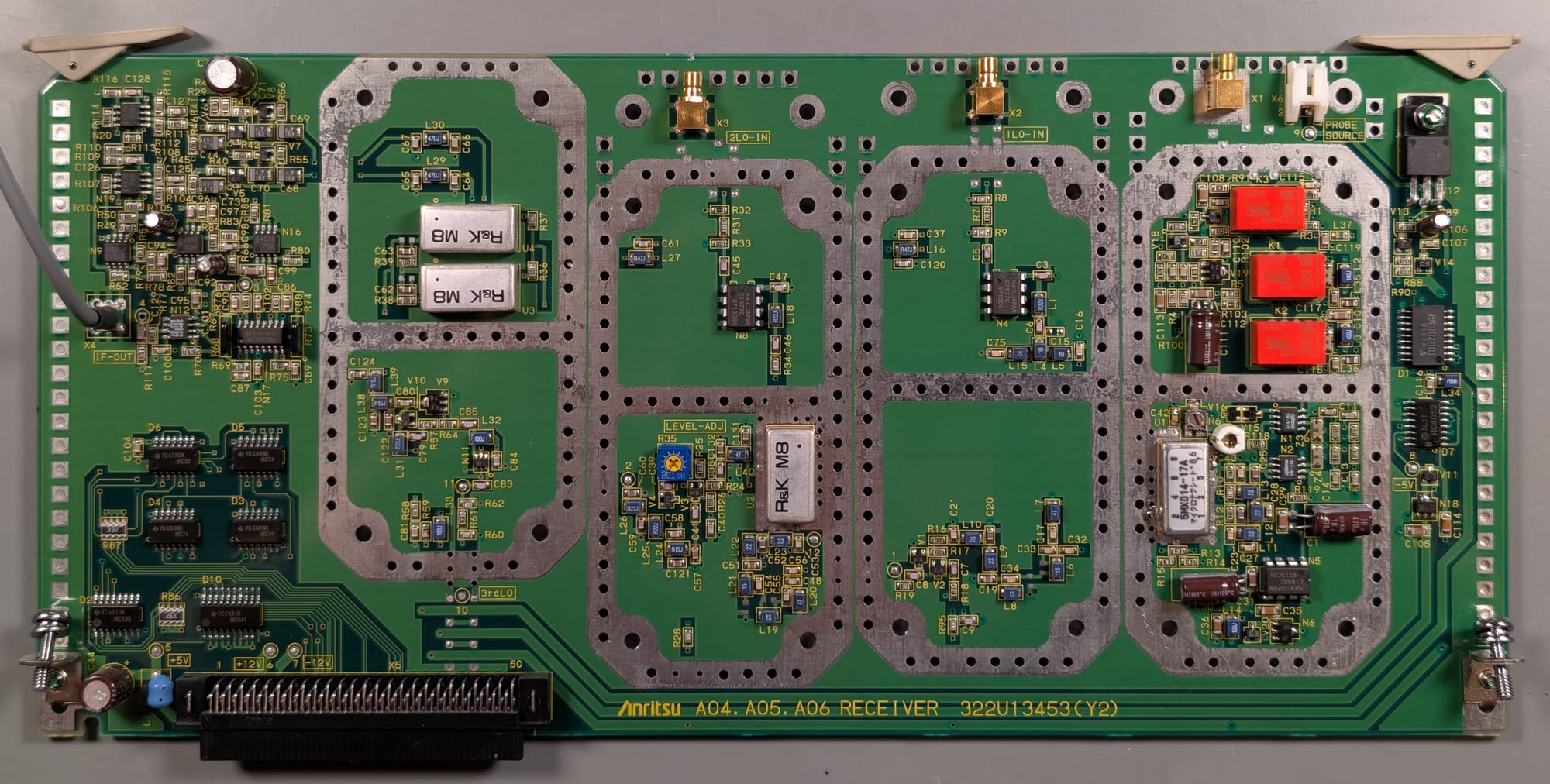
The Receiver modules contain the mixers and filters that downconvert the 10Hz-300MHz received signal to an audio frequency baseband signal that can be captured by the DSP module's ADCs.
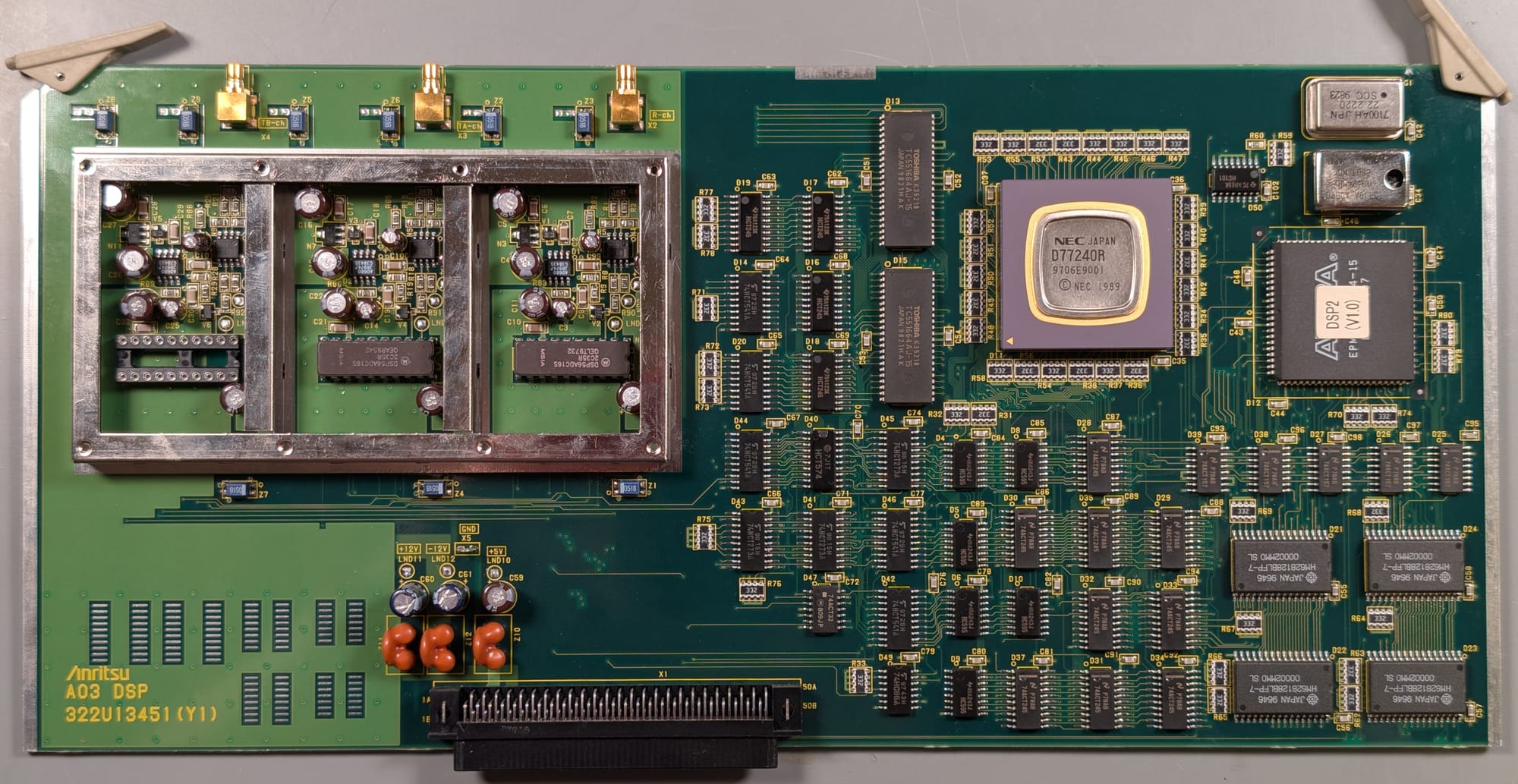
The DSP module contains the ADCs used to capture the baseband signal from the input modules, and contains a specialized DSP chip to perform the additional filtering and processing needed to extract gain and phase information from the baseband ADC signals.
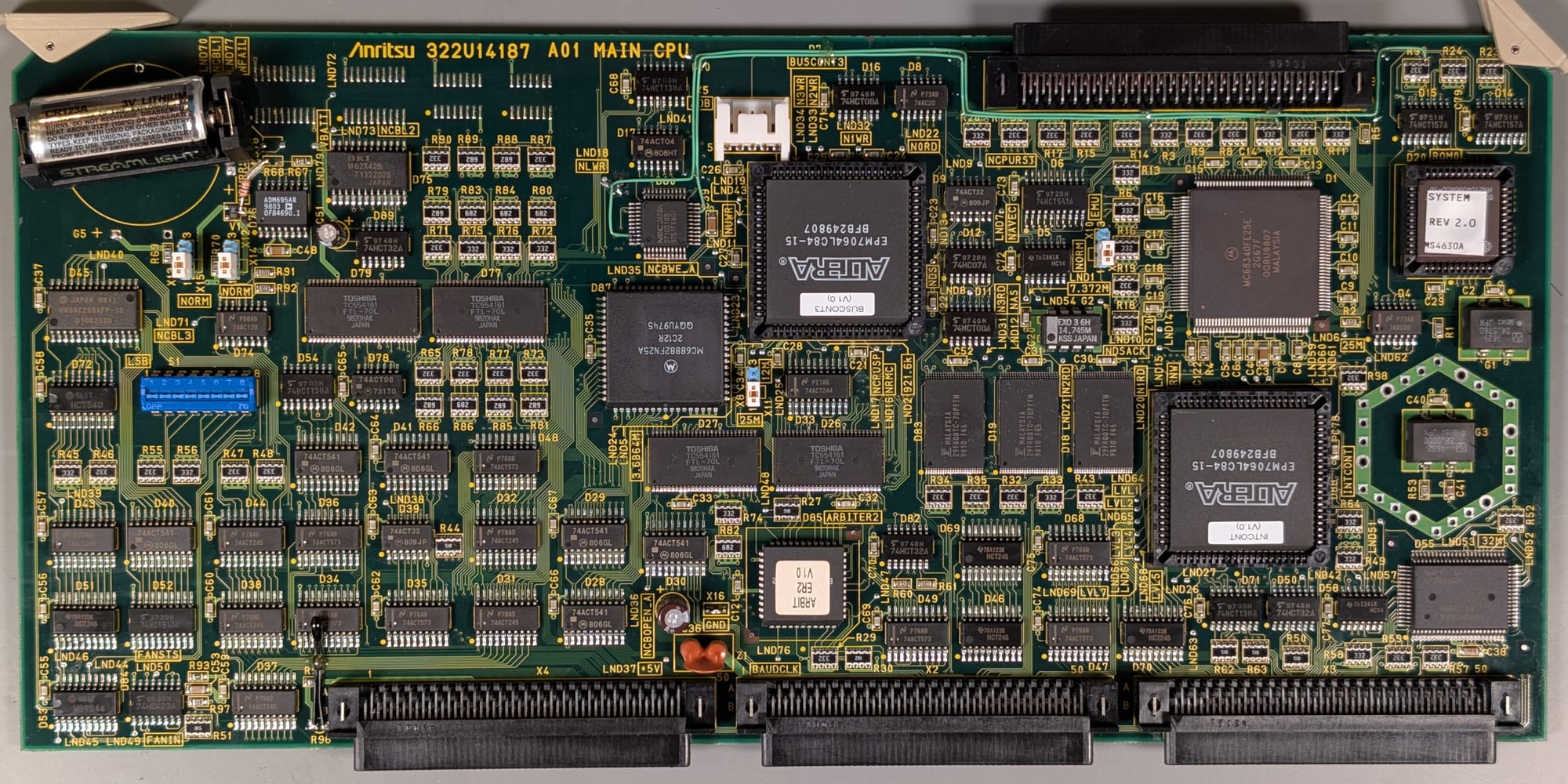
The Main CPU contains the system processor, real time clock and support circuitry to coordinate the overall instrument operation
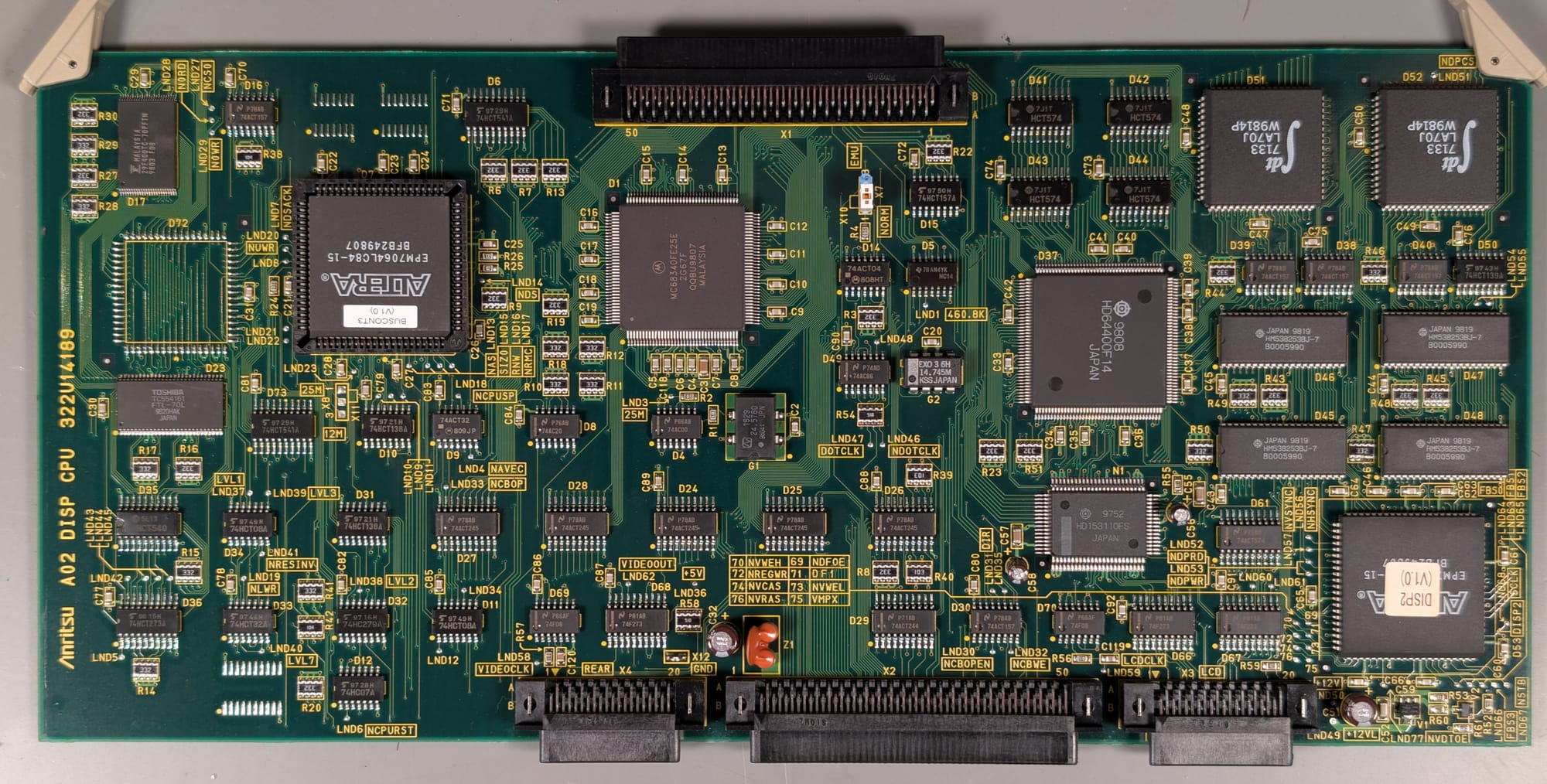
The Display CPU module contains a coprocessor and memory used to handle video generation for the front panel display and rear panel video outputs.

The IO Board contains support circuitry for the rear panel GPIB, video, I/O, and Module Bus connectors. It also contains the external trigger interface.
With at least a rough picture of what's going on inside the network analyzer, let's get deeper into what the actual issue was.
The Issue
The main issue was that the network analyzer wouldn't sweep its output or update the traces on the display. All self-tests passed, reporting no issues, and the instrument responded to control inputs as expected, though attempting a calibration would cause a graphical hang as the instrument waited for completion of a sweep that refused to even start.
Sweeps on this instrument can be initiated either by an internal trigger, which causes the next sweep to begin as soon as the current sweep completes, or by an external trigger, which waits for a signal on the rear panel trigger input before beginning a sweep. To rule out an oddball fault with the internal trigger system, I connected a function generator to the trigger input, but the sweep issue remained.
The instrument does support another sweep mode, allowing manual control over the output frequency via the rotary knob on the front panel. In this mode, I was able to get the output to sweep across frequency, though the displayed trace still refused to update.
A Red Herring
Testing with the manual sweep control seemed to reveal a huge variation in output level across the 10Hz to 300MHz frequency range when measured on my oscilloscope. This made me suspect a possible issue with the Output module at first, potentially with the automatic level control loop. However, re-measuring with a spectrum analyzer showed the output level remained fairly consistent (within a few dB).
This led to my discovery that the hi-resolution acquisition modes on my oscilloscope come with significant frequency limitations and aliasing for high frequency signals. With the hi-resolution mode disabled, the oscilloscope measurements agreed with the spectrum analyzer again.
Fixing The Easy Issues
After some initial quick debug, checking that labeled power supplies were at their expected voltages, I started digging deeper.
Testing with the manual sweep also turned up a couple of simple issues. First was a fault in the output power divider.
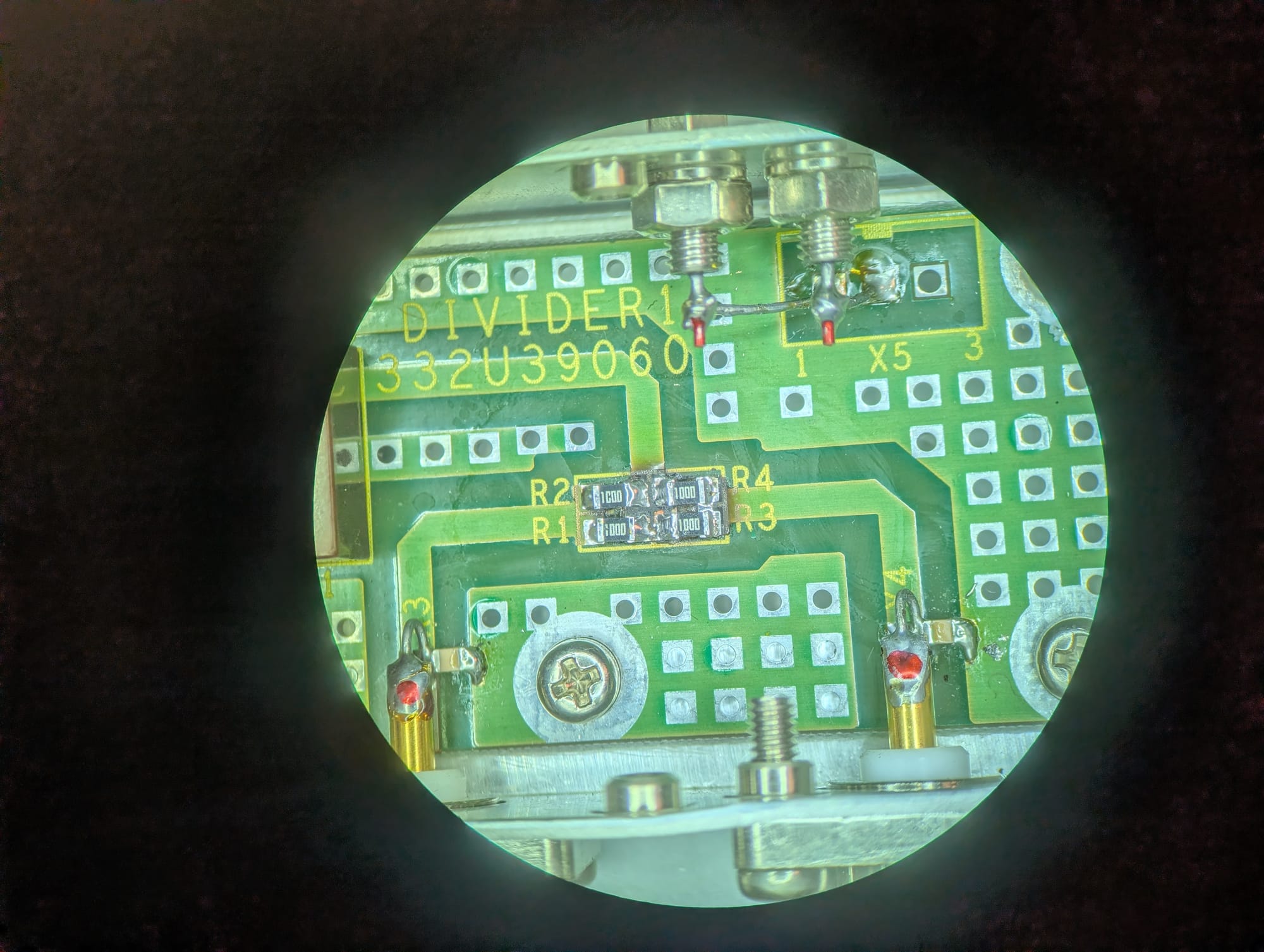
The network analyzer has a built-in power divider to simplify wiring for transfer function measurements, where the output signal has to pass both directly to the reference receiver, and separately through the device under test to the TA receiver.
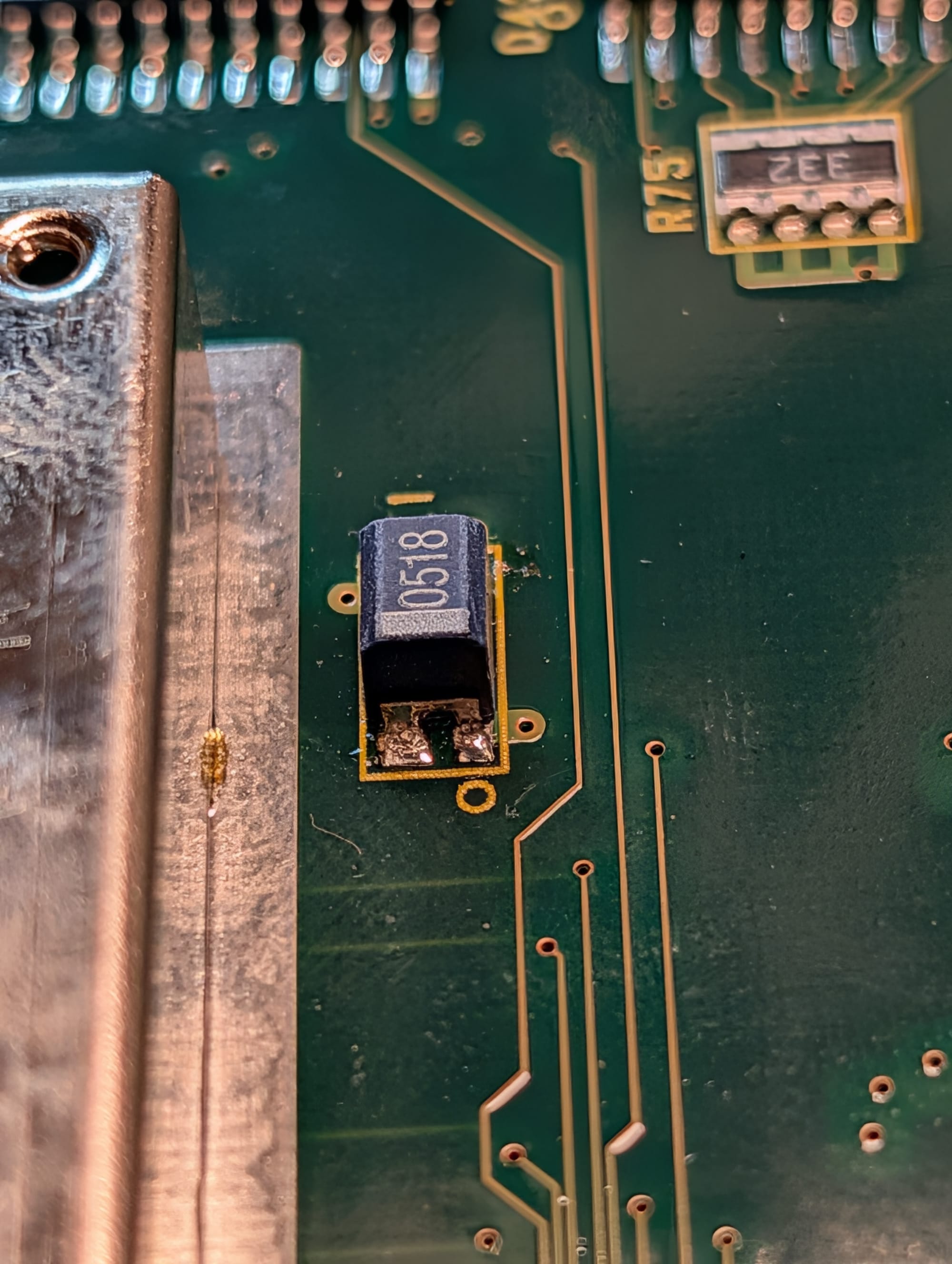
One output from this power divider worked as expected, the other had no output. The reason for this difference was immediately clear:
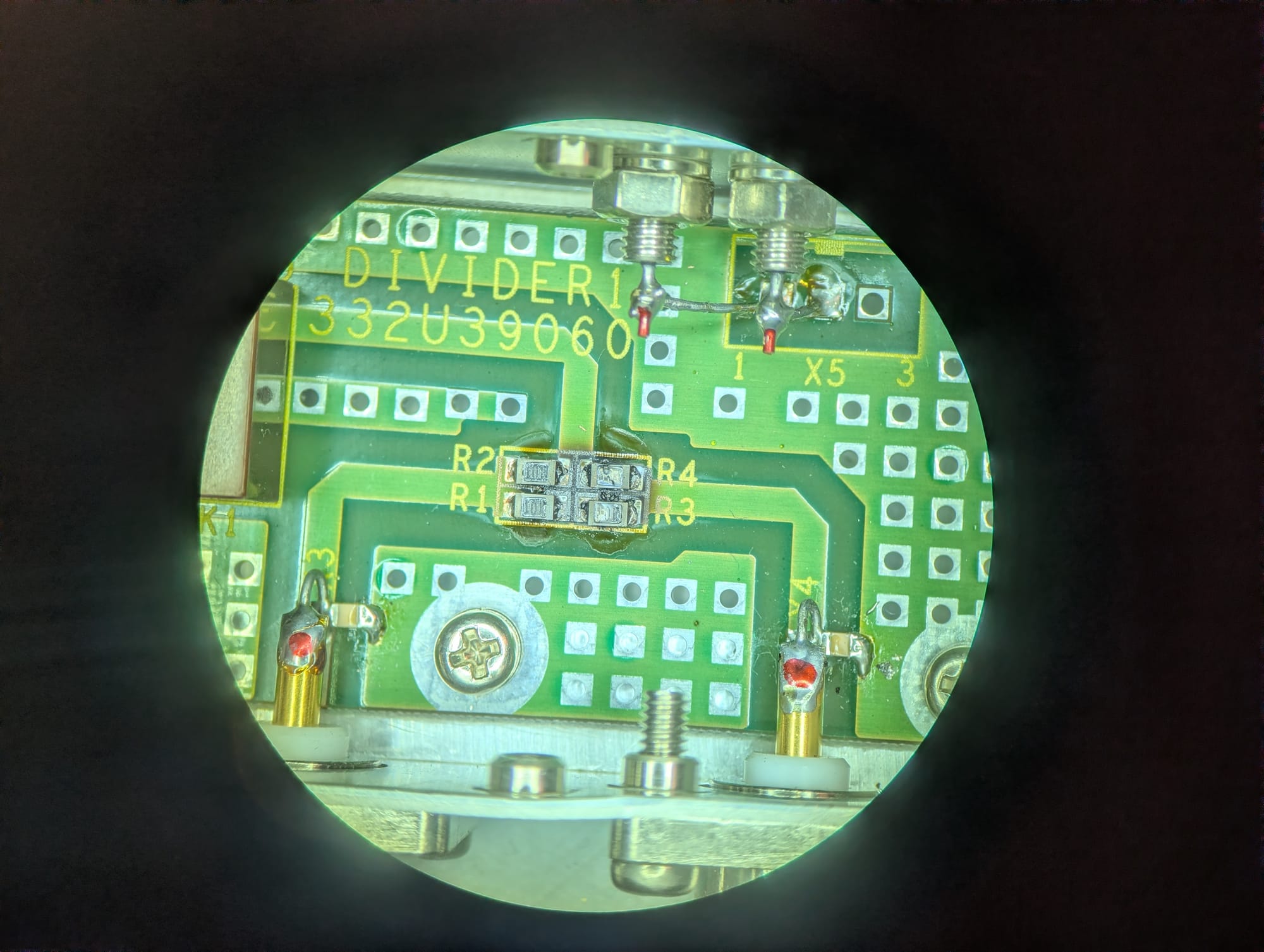
Somewhere in its past, it looks like someone put a little too much power (or, more likely, DC bias) on the left port, absolutely destroying R3 and R4. These dissipated enough power to destroy the resistors themselves, and to char the PCB laminate beneath them. I removed all four resistors, cleaned the damaged PCB laminate, and installed four brand new 100Ω resistors:
After this repair, both outputs worked without issue.
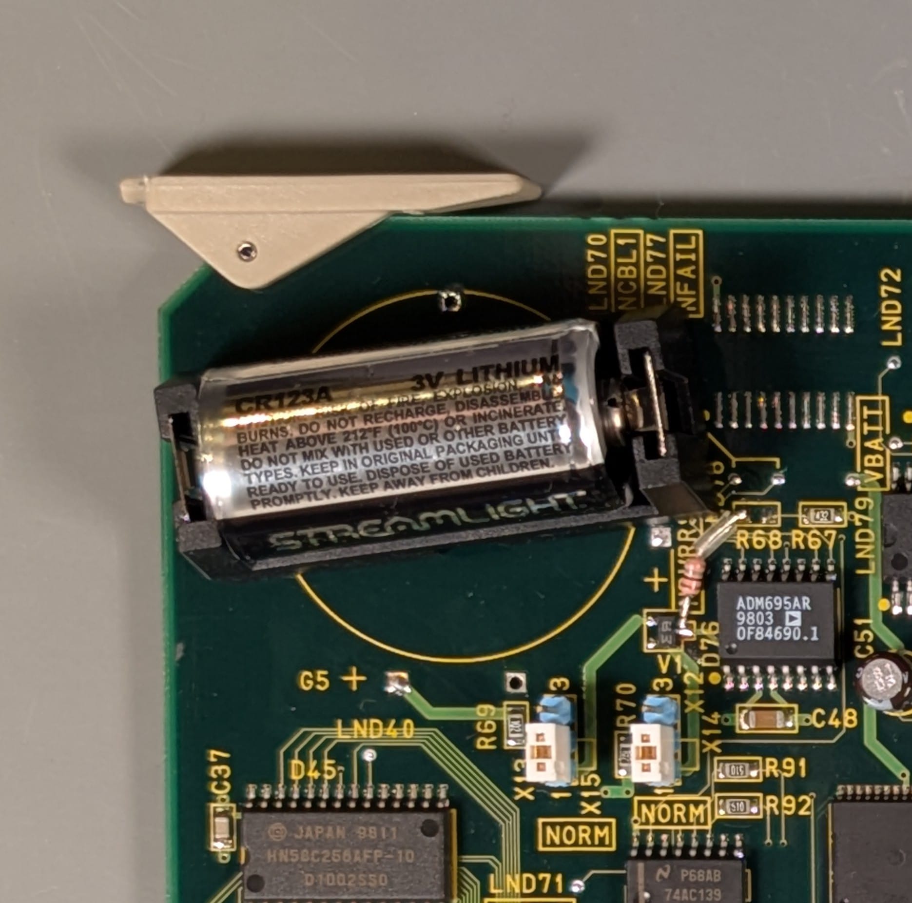
The second issue that was immediately apparent was that the Main CPU module's real time clock battery was completely dead. I was worried I might find one of the infamous Dallas Semiconductor battery-backed RAM/RTC combo chips here. I feared that if there was a battery-backed RAM chip, it could have stored calibration information that could have been the cause of the sweep issue.
Fortunately, all calibration and firmware data on this instrument appears to be stored in nonvolatile storage. The clock battery just provides backup to an OKI M62X42B real-time clock chip.
I replaced the original soldered-on coin cells with a battery holder for a standard CR123 lithium battery, which is absolutely overkill for this application. The CR123 has far more capacity at the same 3V. It'll also be much easier to replace in the future if needed. The install wasn't exactly elegant, but I was able to fit a proper battery holder without covering any other components on the board.
With a fresh battery, the real time clock now keeps time when the instrument is powered off, as expected.
Neither of these fixes solved the sweep issue.
Debugging the Sweep Issue
Thinking through what could cause the sweep issue, I came up with a few possible explanations:
- A fault with the LO module is preventing it from locking, or it isn't sweeping correctly.
- Maybe the reverse power event that damaged the power divider caused damage to the Output module.
- One (or both) of the Receiver modules is damaged.
- Maybe instead of using an internal software interrupt to generate the trigger signal, the internal sweep trigger gets routed into the same circuitry as the external trigger, which might have been damaged.
- The CPU is hung, damaged, or has corrupted firmware.
- I have angered the machine-spirit, and it has not yet forgiven me.
#1 and #2 seemed unlikely. The fact that the output can manually sweep, and has consistent output power across the sweep band indicates the LO is functional and the Output module works as expected. I wouldn't expect that to behave differently in a manual sweep than in an automatic one.
#3 also seemed unlikely. Damage to the receiver module would be more likely to cause inaccurate readings on that receiver, but shouldn't cause sweeps to stop altogether.
#5 didn't seem to have much support either, as the instrument responds appropriately to front panel input.
#6 seemed plausible, but removing the old burnt offerings from the power divider and burning incense failed to placate the machine-spirit and restore functionality, so I decided to consider other possibilities first.
That left possibility #4. To be clear, this was a long shot. I can't think of a good reason to implement the trigger circuitry in this way instead of just handling it with a timer interrupt. I decided to dig into the external trigger circuitry anyways.
The External Trigger Circuit
I removed the I/O module and started tracing out the signal path from the external trigger:
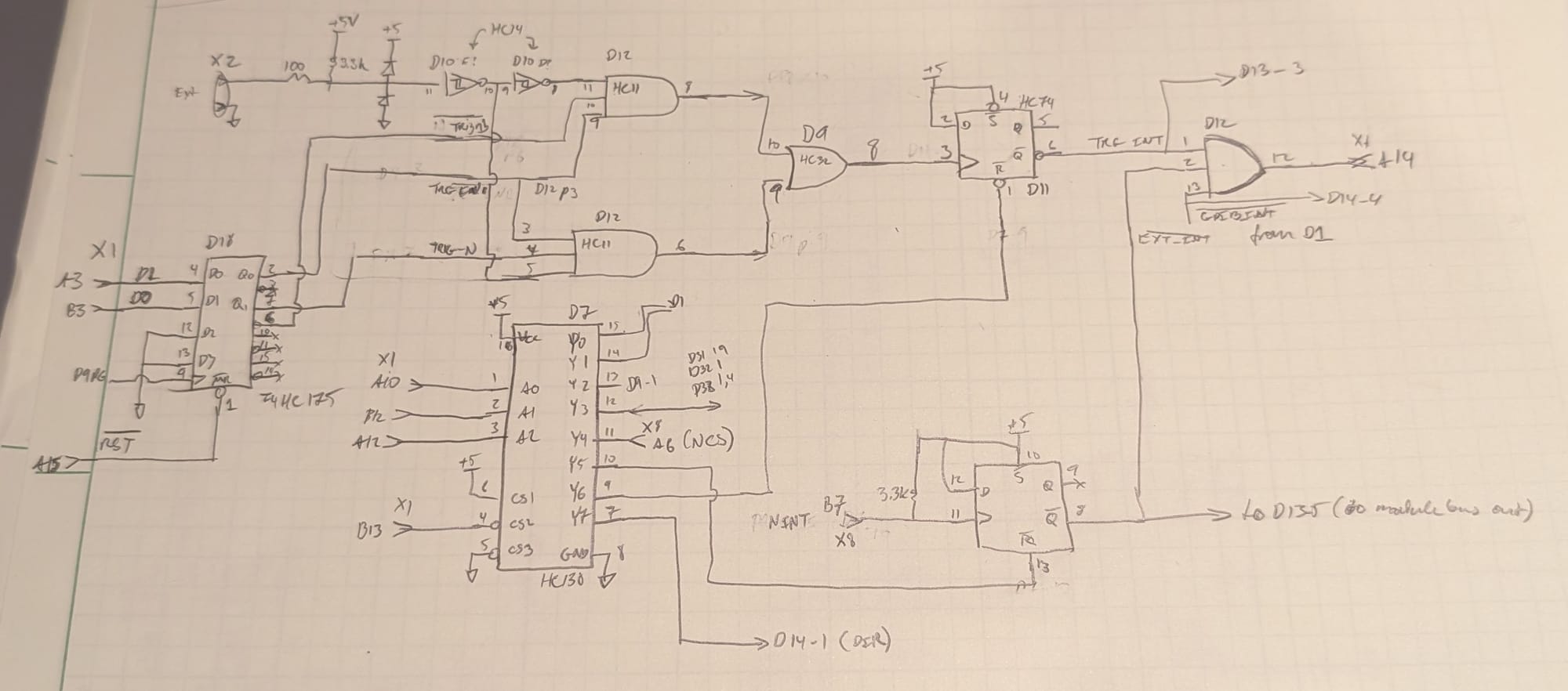
The external trigger comes in through a connector, gets clamped by a Schottky diode pair (V1) to keep it between 0 and 5V, then feeds a cascade of 2 Schmitt trigger inverters (D10) to generate a trigger signal and an inverted copy. These then feed a pair of 3-input AND gates (D12). The other two inputs on the AND gates are provided by a D-type flip-flop (D18) controlled by signals from the main processor bus. One of D18's outputs is an external trigger enable, while the second acts as a polarity select for the trigger.
The output from this enable and polarity select block feeds an OR gate (D9) to combine both polarities and is then used as the clock signal for a separate D-type flip-flop (D11). The active-low output of this flip-flop (conveniently labeled #TRG_INT on the silkscreen) is then combined with two other interrupt lines (#GPIB_INT and #EXT_INT) in an AND gate (D12) before heading off the PCB into the processor bus again.
This works as a processor-polled latch for the interrupt. If the appropriate trigger is received, it causes D11 to shift a '1' to its Q output, and a '0' to its #Q output, setting the interrupt line high. The CPU can then use 3-to-8 line decoder D7 to send a reset signal to D11, causing its Q# output to return to a '1' and clearing the interrupt condition.
With this functionality figured out, and a better idea of where some of the processor bus signals could be found on the various modules, I reassembled the I/O module into the case, connected an external trigger signal, and started probing the trigger signal path.
While the trigger was clearly present all the way up to OR gate D9's output, it appeared that the interrupt was never getting serviced. Furthermore, while I expected to see activity on the processor bus, there was relatively little activity. This was acting like a bus hang, but the instrument was still responsive and, aside from not automatically sweeping, functional.
I visually inspected all three CPU modules, but couldn't see any conspicuous signs of damage.
Tracing The Signal Path
I decided to do a full trace through one of the signal chains (LO to output to receiver to DSP) and see if everything along that path looked correct. I hoped to both get a better idea of how the instrument worked, and possibly rule out a fault with the bus interface on one of the modules that could explain the hung interrupt. The LO and output signals behaved as expected, and under manual control, both swept around just fine. I decided to check the output from the receiver to the DSP, and found that it, too, seemed to be fully functional, with a clean-looking signal around 20kHz.
With signal all the way to the DSP board, but no update to the measured trace, I decided to see if the ADC for that receiver was working as expected. Since the boards aren't accessible when installed in the chassis, I soldered jumpers onto all the key ADC signals for the 'R' channel (ADC clock, sample clock, data, and analog input) so I could clip test leads on outside the chassis.
To my surprise, the signal at the ADC input showed no differences from the signal at the Receiver output, but there was no data coming out of the ADC. Stranger still, the ADC outputs appeared stuck at around 1.8V, despite all logic in this unit being 5V TTL.
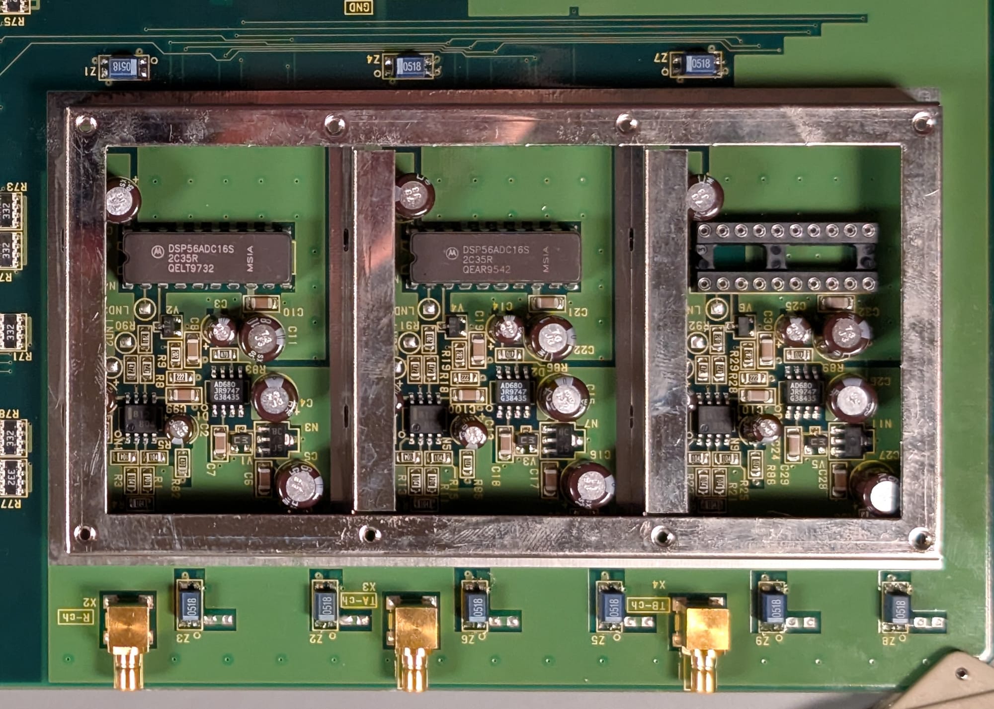
Each receiver channel feeds into its own Motorola DSP56ADC16S 16-bit Sigma-Delta ADC. To ensure the best possible isolation between channels, each is within a separate shielded compartment, and has feedthrough filters (blue components Z1-Z9 above and below the can) on all power supplies. The analog supply voltage to each ADC is sub-regulated off of the +12V analog supply, which in turn feeds a precision voltage reference for each ADC.
I soldered additional test connections to all of the ADC power supply pins, and found that, while all of the analog supplies checked out okay, the digital supply was completely absent.
I started tracing continuity through the +5V supply and found that there was no connection from the +5V input to the board to the +5V supply pin of the ADC, but when probing across the filter, I did still see continuity. Sometimes. But only if I had the probes at exactly the right angle. It was getting very late, and I decided to give the board one last visual check to see if I could notice anything obvious.
The supply input on the +5V digital filter had a cracked solder joint. If I bridged the joint with my DMM probe, it would measure just fine, but probing at a slightly different angle, I'd see no continuity.
I took the board to my soldering bench, reworked that joint, installed the board back into the instrument, hit the power button, and was met with a functioning, sweeping instrument!
Action Shots
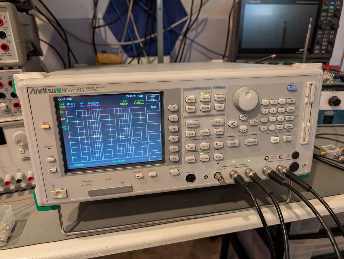
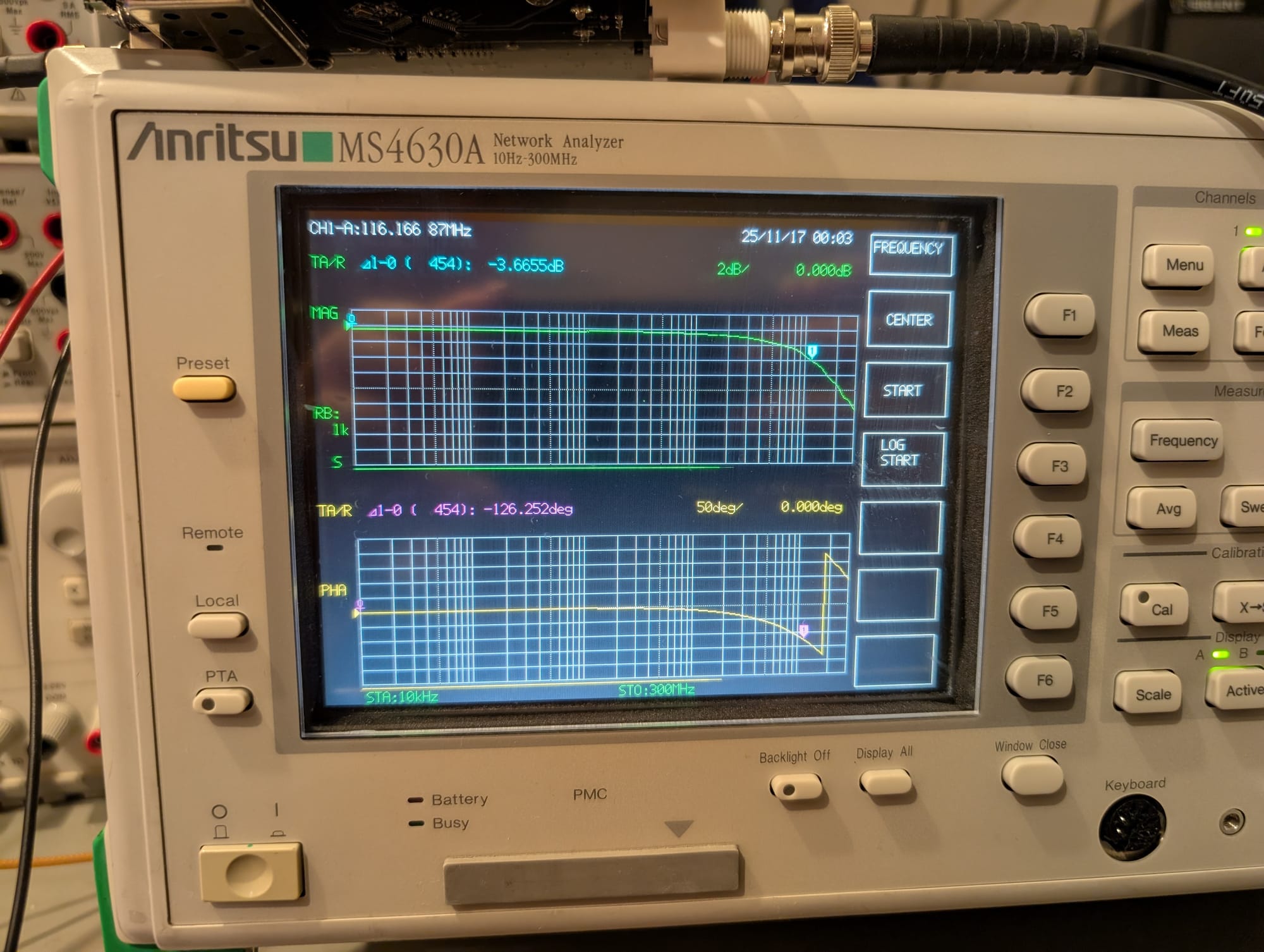
The next day, after taking pictures of the front and back of each major module in the instrument, I reassembled it and did some testing. After doing a thru calibration, I connected the network analyzer across one of my Power Rail Probes:
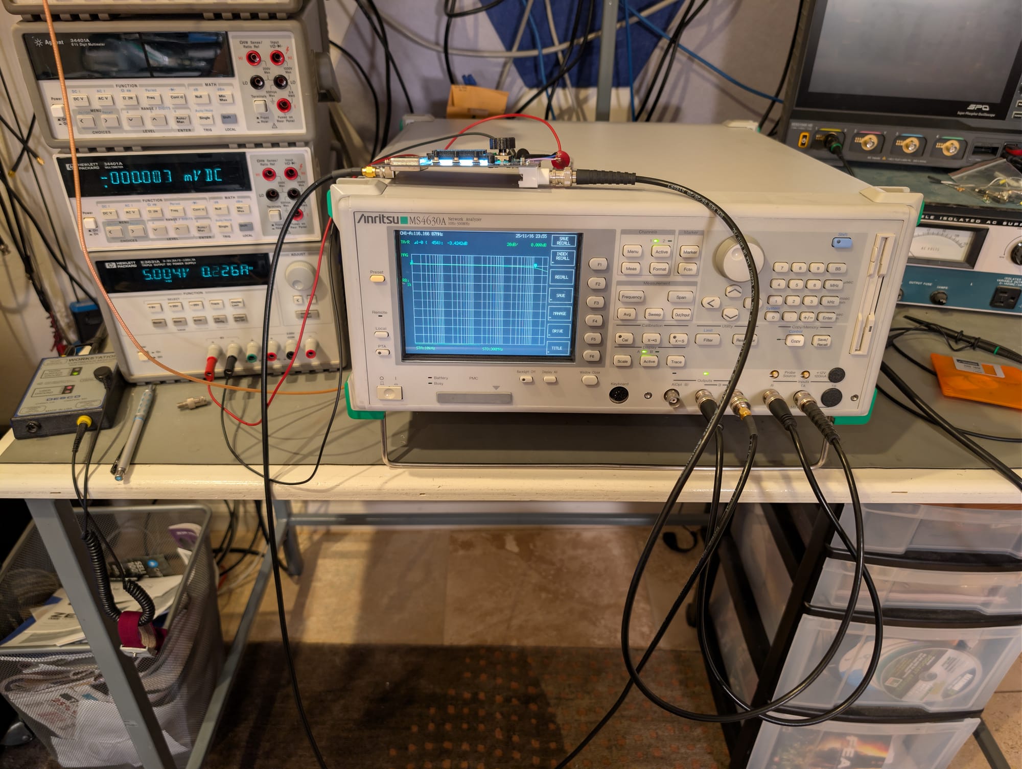
And got a good measurement of its frequency response, both in magnitude and phase:
So, what went wrong?
A slightly iffy solder joint eventually cracked, possibly due to vibration or being dropped in transport. That crack interrupted the digital supply to one of the ADCs.
The Sigma-Delta ADC architecture used here doesn't have a "sample" input to trigger conversion. Instead, it continuously converts the input signal and emits clock, data, and frame-sync signals that contain the output sample stream. With no digital supply to one of the ADCs, it wasn't generating these signals. It appears that the DSP module hangs if no clock is received from an ADC, and this hang was not detected by the power-on self-test.
It appears to hang enough of the system to also affect interrupt handling by the main CPU but doesn't hang enough of the system to prevent the front panel controls or display from working.
What's left to do?
While the instrument works well, I'd love to find another donor parts unit to add the optional TB channel and the mechanical attenuator for the output. Neither are features I need, the heart just wants what the heart wants.
What I do absolutely need is a way to get measurements off of the instrument. I'm fortunate enough to have a GPIB setup for my lab, so I'll probably end up writing a Python module to wrap the SCPI commands in a nicer looking interface.
The 3 1/2" floppy drive seems to be damaged (or the lone disk I could find laying around no longer works). Any attempt to read or write files on it throws up a Media Error. I'd like to either replace the drive with a working floppy, or get one of those floppy interface to SD-card or USB adapters as a more modern replacement.
Conclusion
This was one of the coolest repairs I think I've ever done. Realizing I've reached a point as an engineer where I was able to diagnose and repair this without any service manuals was tremendously gratifying.
I'm not sure I'll buy any more Anritsu gear, though, which is a real shame. The build quality is very nice, and the instrument itself is a joy to use. The absolute lack of any support for repairs is really unforgivable in my opinion, however. I reached out to Anritsu to see if any service information was available. I knew getting full schematics was almost certainly not going to happen, but having a calibration guide or troubleshooting manual would have been helpful.
To their credit and my immense surprise, Anritsu's customer support team did reply promptly and politely to my support request, despite me really not being a paying customer. Truth be told, I expected to hear nothing at all from them except to be put on a marketing email list.
Unfortunately, their reply was to inform me that the instrument was no longer supported (as of 2008) and that all service manuals, schematics, and any other documents were company confidential. That includes calibration procedures, which is - in my eyes - unforgivable.
If the only calibration option for their gear is through the factory, and no independent lab support is possible, that really calls into question for me the possible service lifetime for their gear. My unit was built around 1998, and apparently stopped being supported at all in 2008, 10 years later. That's a tragedy of a lifespan for something like this.
I think if I was doing work with their instruments that was right at the cutting edge, where I wasn't keeping an instrument around for 5 years, much less 10, I might have a different view on this, of course. But that's not the kind of work I'm doing in my lab, and right now, even a nearly 30-year-old instrument is more than adequate for my needs.
So, in closing, and with all due respect, Anritsu, eat your heart out: